High Voltage / Piezo Amplifiers & Signal Conditioners
Fiber Optic Links / Data Acquisition Systems
RF Power Amplifiers / Dual Directional Couplers
Instruments for Biological Science
Under Water Metal Detectors, Camera’s & Sonar Systems
|
Gas Sensors / Mixers / Pumps / Other Sensors:

GSS Gas Switching Systems
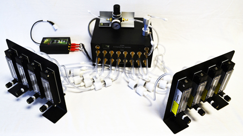
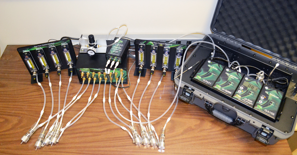
When Gas Switching System is used with a Q-Box Package the Larger Flow Gas Pump (Q-P651) is used (3LPM No Load). It carries the reference gas via the G261 Low Pressure Regulator to the flowmeters. Each flowmeter supplies and manually controls the flow of gas to each sample chamber. Output gas from all sample chambers is carried to the gas inputs on the gas switcher (G244 or G243). The specific chamber is selected by the software and its gas is carried to the analyzers and the flow monitor of the Q-Box via a solenoid valve associated with that channel inside the gas switcher. The switching between chambers is controlled via the Digital Control Unit (C200) and the software. The output from the remaining chambers vents via the gas switcher vent ports to the atmosphere. As a result all chambers have gas flowing past the sample at all times. Channel 1 is always used as a reference channel. This is Open Flow setup.
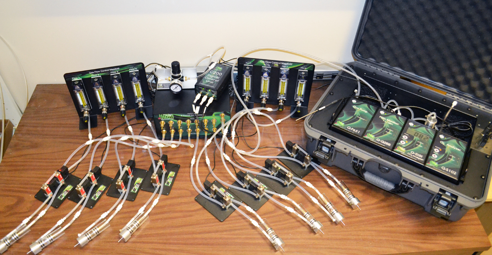
The Gas Switching System can also be provided in enhanced version for both Open-Flow and Stop-Flow Measurements. Stop-Flow is employed when measuring small, inactive samples, i.e. single insects. Each chamber is associated with a solenoid assembly (A380) of two 3-way valves, which is activated to stop flow through the chamber and allow accumulation of CO2 and depletion of O2. When the valves become deactivated the gas from the chamber is swept through the gas analyzers of the Q-Box for measurements. Stop-Flow setup provides more sensitive configuration.
- Stop-Flow Setup for 8-Channel System:
- Open-Flow Setup for 8-Channel System:
Three modes of operation are available for the gas switching system. Mode 0 allows sequential measurements of all channels from 1 to 8 (in eight channel system) with reference channel being measured every 8 Channels. Mode 1 allows sequential measurements of all channels with the reference channel being measured after each sample channel. In this mode the reference signal is measured more frequently. User can select the No of Channels, Mode, Dwell Time (on each channel) and EventTime (time period for calculating of average data at the end of each DwellTime) in the software. Manual Mode can also be selected in user parameter ManualCh to allow monitoring of a single channel during the setup of an experiment.
- Features:
- Four or Eight Channel Gas Switching Systems
- Measurements of Gas Exchange in Multiple Organisms with One Set of Analyzers
- Software Control, Data Collection and Final Calculations
- Final Calculated Data Displayed by Channel
- Applications:
- Measurements of Multiple Samples with One Set of Gas Analyzers
- Photosynthesis and Plant Respiration
- Animal Respiration
- Insect Respiration
- Soil Respiration
- Nitrogen Fixation
- Headspace Gas Analysis above Water Sample
- Components:
- G244 Eight Channel Gas Switcher in GSS-8 OR G243 Four Channel Gas Switcher in GSS-4
- C200 Digital Control Unit
- Flowmeters (8 OR 4)
- G261 Low Pressure Regulator
- Eight or Four A380 Solenoid Valve Assemblies for Stop-flow Measurements (Enhanced GSS)
- Tubing and Connectors
- Customized Experimental Files (Logger Pro)
- Flow-through Chambers (Optional)
- Software:
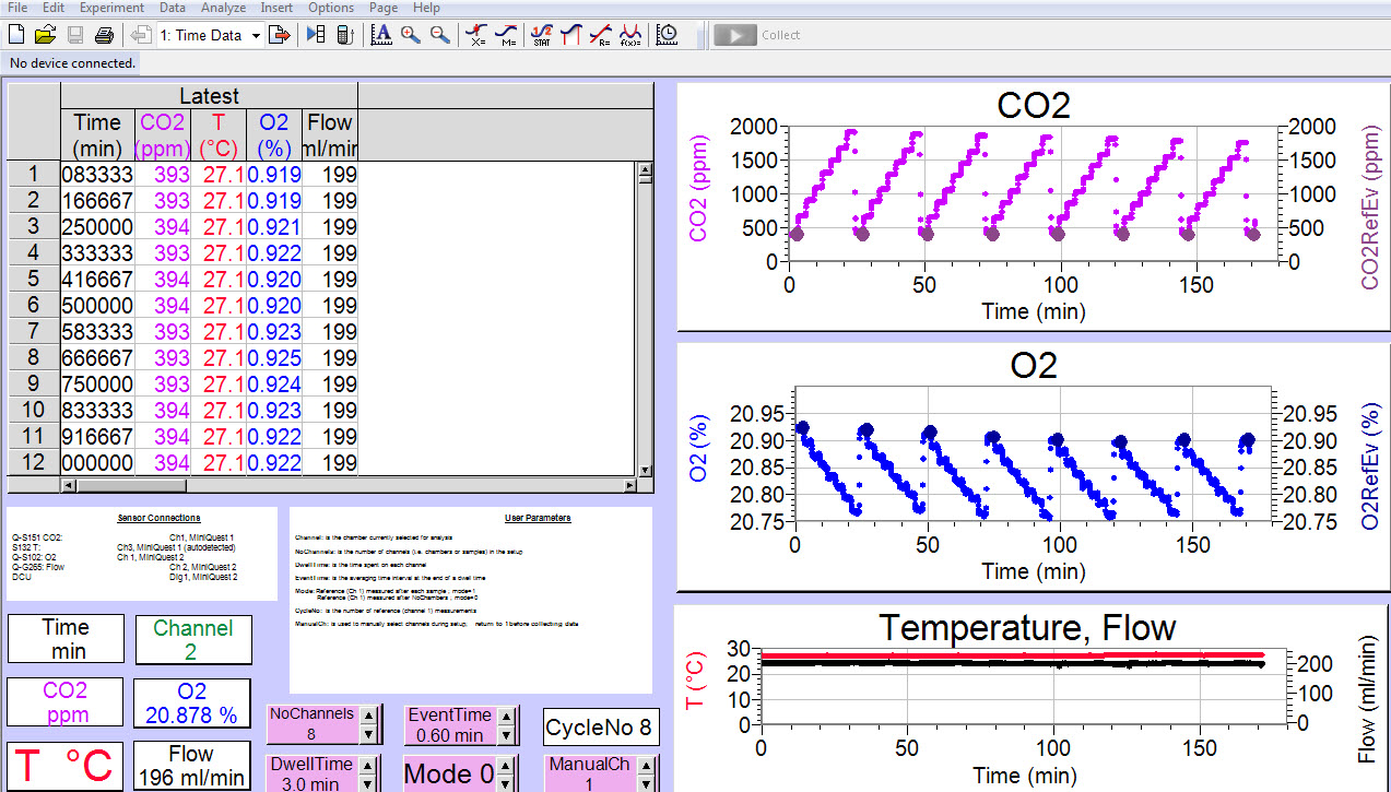
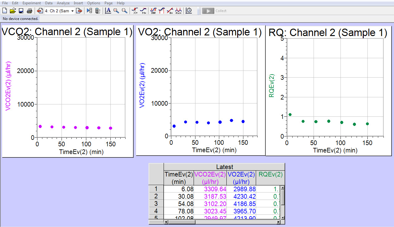
Software allows viewing of data by channel and provides direct calculations of the key parameters such as VO2, VCO2 and RQ (when used with Q-Box RP1LP and Q-Box RP2LP Packages).
All Specifications are subject to change without a Prior Notice
For any sort of clarifications kindly contact:
info@globesolutionz.com
|