High Voltage / Piezo Amplifiers & Signal Conditioners
Fiber Optic Links / Data Acquisition Systems
RF Power Amplifiers / Dual Directional Couplers
Instruments for Biological Science
Under Water Metal Detectors, Camera’s & Sonar Systems
|
Thermal Anemometry
AN - 2000 Hot-Wire / Hot-Film Anemometry System
The AN-2000 Hot-Wire and Hot-Film Anemometry System is a Smart Hot-Wire & Hot-Film Anemometer, used for Measuring Fluid and Gas Velocity. This Anemometry System is a Complete Automated Solution, with Computer Interface and Software. The System has many Unique Capabilities, making it Suitable for Measuring the Most Complicated Flow Conditions.
- Among it’s Features are:
- Multi Sensor System: upto 16 Channels
- Simultaneous Measurements: for Important Phase Information
- Calibrated Filters: Precision Cut-off Frequency and Same Delay on All Channels
- Multiple Triggering and Synchronization Options
- 4 Bridge Ratios: for All kinds of Sensors
- Optical Synchronization: for Doing Ensemble Averaging of Flow (Propellers, Fans and Other Rotational Systems)
- High Speed Interface: 480 Mb/Sec - For High Sampling Rates
- Windows XP Software, LabView Interface
- Outputs Digital Data in Engineering Units (Linearized) - Excellent for Flow Control and Feedback Systems
- Measurement of Velocity, Temperature and External Voltages Simultaneously
- New Features: USB-2 Interface, High Speed A2D - 500kHz per Channel, Windows XP Compatible Software
- Introduction:
An Anemometer is an Instrument for Measuring Fluid Velocity, whether it be of Gases or Fluids, Hot-Wire or Hot-Film, Anemometers measure Fluid Speed using a Delicate Probe made of Thin Tungsten / Platinum Wire, or a Thin Metallic Film. This Probe is Heated to a Temperature Higher than Average Temperature of the Fluid. Using Sophisticated Circuitry, the Anemometer Stabilizes and Maintains the Probe Temperature at a Constant Level throughout the Measurement. Since the Fluid flowing past the Probe has a Lower Temperature than the Probe, the Film / Wire is Constantly being Cooled by the Fluid Flow. The Higher the Velocity, the Faster the Rate of Cooling.
Since the Anemometer must Maintain the Probe Temperature at a Constant Level, it is therefore Sensitive to the Rate at which it is being Cooled, i.e. the Fluid Velocity. This Velocity is Translated to a Continuously Changing Voltage which has a Nonlinear Relationship with the Flowing Fluid. This Voltage then undergoes Signal Conditioning, to Filter out Noise and Improve the Signal / Noise Ratio.
After Proper Calibration of the Probe Channels, it is possible to measure Fluid Velocities with an Accuracy of 0.05% or Greater, depending upon the Measurement range and the Quality of the Calibration. The Response Time between Measurement and Instrument Output is Very Short in Comparison with Other Methods of Fluid Flow Measurement and can reach a minimum of ½ µSec (half microsecond). The AN - 2000 Anemometry System measures at that Speed upto 16 Channels Simultaneously!
- AN - 2000 High Speed USB-2 Interface:
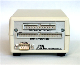 |
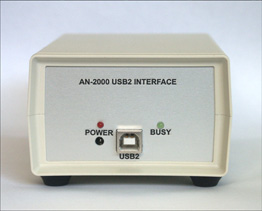 |
AN - 2000 High Speed USB-2 Interface
(AN - Side) |
AN - 2000 High Speed USB-2 Interface
(PC - Side) |
- Outstanding Features:
- A User-friendly Remote Controlled Anemometry System
- PC Interface Card, DOS and WINDOWS (3.1 & 95) Software, LABVIEW Interface
- Automatic Bridge Balance, Automatic Frequency Compensation
- Built-in Digital Oscilloscope and Data Acquisition System
- Built-in Artificial Intelligence, for Easy Operation
- Built-in Digital Linearizer - Outputs Raw Data in Engineering Units:
- No Added Noise
- No Drift
- Real-time Data
- 15-bit Resolution
- Automatic Fast Calibration using the CAL - 2000 Digital Air-Speed Calibrator.
- Temperature and Humidity recording for Compensation
- Advantages of AN - 2000 Anemometer System:
The AN - 2000 can measure Fluid Velocities Ranging from 0 to 150 m/sec, as well as Supersonic Measurements. In Addition to these Inherent Qualities of the basic AN - 2000 System, there are 14 Extra Options which can be Added to Any Number of Channels. These Expand the Capabilities of the System, Allowing it to make Professional-Standard Measurements in Different kinds of Fluids.
Another Advantage of the AN - 2000 is it’s Modularity: Channels can be Removed or Interchanged without Disturbing Other Channels already Calibrated for Different Experiments.
The AN-2000 is being used today at a Large Number of Leading Research Institutes and Universities throughout the World, where for a Number of Years, it has Proved its Value as a Reliable and Accurate Instrument and has become a Valuable Research Tool for Scientists and Engineers. Part of the AN - 2000’s Success is due to its User-oriented Design, making the System Easy and Straightforward to use by Inexperienced Students and Professional Researchers alike. We hope that you become part of this Expanding Group of satisfied AN - 2000 Users.
Refer to the Technical Specification to find out about the Outstanding Capabilities and Characteristics of the AN - 2000.
- Description:
State-of-the-art Microprocessor Architecture, based on a Fast Processor, gives the AN - 2000 the Ability to Perform High Speed Display and Control Operations as well as Complicated Floating-point Calculations. Data Acquisition is Performed by a Proprietary Hardware designed for High Reliability DMA Transfers at High Rates.
The USB-2 Interface is a High Performance Multi-function Interface Hardware, that combines High Speed DMA Interface, RS-232 Serial Communication and a Fast Display Output Port. It uses Direct-Memory-Access Transfers combined with an Ultrafast FIFO Buffer to Achieve High Speed Data Acquisition rates upto 20 Mbytes/Sec. Fully Compatible RS-232 Port Controls the Operation of the Instrument. The High-speed Display Port provides Continuous On-line view of the AN-2000 Display on your PC’s Screen. This Interface would work with Any Desktop or Portable PC Computer and even on a Mac, using a Windows Emulator.
AN - 2000 Interactive Graphics user’s Software Packaged is designed to have the Look and Feel of a Physical Instrument. Ready-to-go, Easy to Control Menu Options provide Full Control over the AN - 2000 Anemometry System, the USB-2 Interface and other Data Communication Interfaces as well.
AN-FLOW is a complete Software System for Data Acquisition, Instrument Control, Digital Signal Processing, Data Analysis, Graphing and Data Presentation. This Menu-driven Software has Many Powerful Functions used for the Analysis of Anemometry Signals as: Linearization of Data, Polynomial Calculations, Calibration of 1, 2 and 3 Component Probes, Real-time Display of Acquired Data, Time-window Display, FFT, Correlation, Histograms, Averaging, Turbulence Intensity, etc.
- Controls and Indicators:
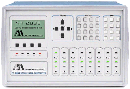
GRAPHIC DISPLAY: |
The High Resolution Dot Matrix Display provides a Detailed and Clear Interface for Communication between the User and the Anemometer. The built-in Software is Controlled by a Hierarchical Menu System which gives Direct Access to System Functions. At Every Option the User is Assisted by Context Sensitive Help at the Touch of a Button. Frequency and Impulse Response Plots can be Plotted Easily and a Storage Scope can be used to Observe Measured Signals. On all Plots and Graphs, the Cursor Keys allow the Immediate Display of Corresponding Values Measuring Time, Frequency, Voltage, etc. |
MENU KEYS: |
The Menu Keys enable Varied Functions depending on the Menu Displayed on the Screen. The Corresponding Functions Appear above Each Key Providing Convenient, Flexible and Easy Operation. |
STATUS LIGHT: |
The Status Light Indicates System Status. During Remote Operation this provides an online Indication of the Operation Mode. |
CURSORS: |
The General Purpose Cursor Keys Allow:
- Selection of Data Points on Graphs for Measurements of Amplitude Frequency and Time
- Amendment of the DC Offset & Gain or Timebase ’ Amplitude
- Selection of Channels and Menu Options
|
FUNCTION KEYS: |
16 Powerful Functions give the User Direct Access to Instrument Control by Accessing the Various Options throughout the Menu Hierarchy.
The EXTEND Key Removes Graph Axes and provides Maximum Resolution by Extending the View Vantage to the Whole Screen Display.
The HELP Key Activates Context-sensitive Information and Operating Instructions at Every Menu Screen.
The SETUP Functions used to Select Parameters for Instrument Configuration. All Parameters are Stored in Non-volatile Memory and therefore render Re-entry of Data Redundant should Power to the Anemometer be discontinued.
The OPERATE and STANDBY Keys Help Protect the Probes by Connecting or Disconnecting the Sensor Loop via the Soft Start Protection Circuit Installed on Each Channel, Preventing Probe Burn-out by any cause. |
NUMERIC KEYPAD: |
The Numeric Keypad is used for Manual Input of Various Data Values Including: Cable, Probe Resistance, Overheat Ratios, Gain, Offset, Calibration, Graph Points, etc. These Parameters can also be input from a Host Computer through the RS-232 Standard Communication Interface and Stored in Memory. |
CHANNELS: |
The AN - 2000 supports upto 8 Channel Modules, 16 with the Expansion Unit. Each Module has 4 LED Indicators showing Channel Status: SELECT indicates Channel Selected; BALANCE indicates Bridge Balance. The OPERATE Light, when On, Demonstrates that the Probe is Operating, Off when Probe Operation is Discontinued by the User or the Automatic Burn-out Protection Circuit. The CABLE COMPENSATION Accommodates Cable Lengths of 5 to 15 meters. |
- The Intelligence Behind the Solution:
The Combination of Advanced Silicon Technology with A.A Lab Systems Experience, provides Research and Industry with the Best in Fluid Measurement Instrumentation. This System allows Accurate and Automatic Measurement of Any Type of Fluid Flow in Gases and Liquids using Hot-Wire or Hot-Film Probes.
Unlike Other Anemometers, the AN - 2000 uses a Custom Integrated, built-in Menu System to Help Automate Otherwise Tedious Procedures, such as Bridge-balance, Resistance Measurement and Frequency Compensation. The Integration of Advanced Software with a High Quality Measurement System makes the AN - 2000 a Complete Solution for all your Fluid Measurement Requirements.
CABLE RESISTANCE |
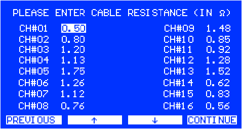 |
The Cable Resistance is Measured Automatically by Connecting a Shorting Probe. Values may also be Entered Manually for Probes which cannot be Disassembled. Cable Resistance Ranges from 0.1 to 15Ω (Ohms). |
PROBE RESISTANCE DISPLAY |
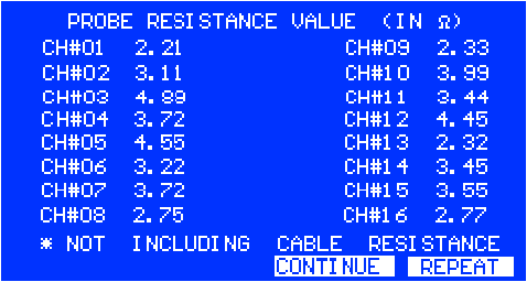 |
The Probe’s Resistance is Automatically Measured for both 1:1 and 1:10 Bridges. Net Resistance (Without Cable) is Calculated within 0.01Ω (Ohms) Accuracy and the Probe Resistance Values are Displayed for Inspection. By Pressing REPEAT, the User may Re-enter or Re-measure Values. |
OVERHEAT RATIO |
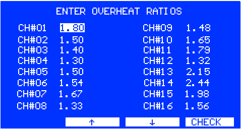 |
Overheat Ratios for Each Channel (or a Single Ratio for All Channels) are Entered. The Values are Stored in a Non-volatile Memory. The CHECK Function runs a Logical Check of All Values and will Notify the user of Any Errors. |
TEST OK |
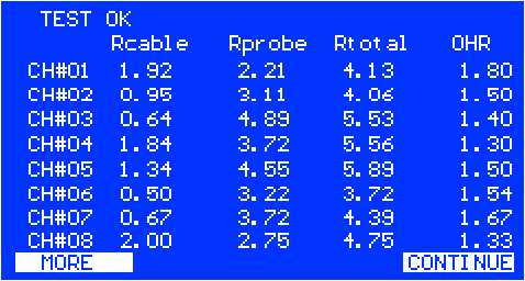 |
Upon Successful completion of Measurements and Analysis, the following Values are Displayed for Each Channel: Cable and Probe Resistance Values, Total Resistance and Overheat Ratio. |
T.O.B. VOLTAGES |
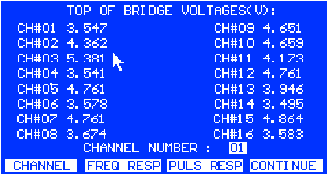 |
Top of Bridge (T.O.B) Voltages for All Channels are Measured after Probes have been Operated. |
PULSE RESPONSE |
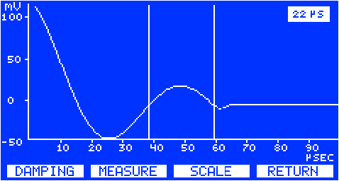 |
A Pulse is Transmitted to the Bridge and the Pulse Response of the Selected Channel is Displayed on the Screen. The Time Base, Offset, and Amplitude can be Varied and the Response can be Measured Precisely with the Use of the Cursor Keys. The channel’s Damping Factor can be Adjusted while the Pulse Response is Displayed. |
GAIN & DC OFFSET |
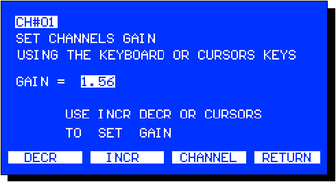 |
Any Number of Channels can be Selected for Calibration of Gain and DC Offset. Gain & Offset can be Configured Manually or Calculated Automatically according to your A/D Range. |
FILTERING |
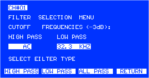 |
At any time during Measurement, a Fourth Order Butterworth Filter can be Applied to the Probe Signal. Any combination of Low and High-pass Filtering can be Selected from a Range of Filter Frequencies. All Filters, in all Channels are
Automatically Calibrated to provide the same Cutoff Frequency and Delay. |
SCOPE MODE |
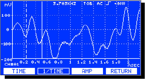 |
A built-in Digital Oscilloscope Permits Real-time Observation of Any Channel and Includes Functions for Freezing and Measuring Signal Waveforms. |
DIGITAL LINEARIZATION |
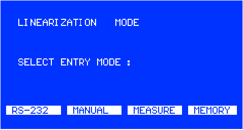 |
The Measured Probe Signal can be Processed in Real Time using a Transform Polynomial, producing Immediate Readings of Fluid Velocity and Temperature.
The Polynomial is Unique for Each Channel and can be either defined Manually, Calculated from Data Points using Least Square Fit, or downloaded from the Host Computer. |
BODE PLOT |
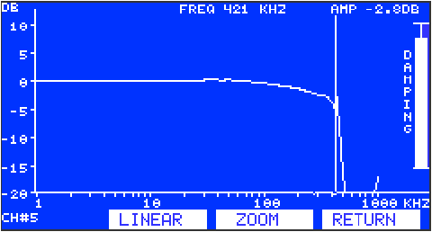 |
By sending a Calibrated Sine Wave to any Selected Channel, the Bridge Response can be Plotted on the Graphic Screen using a Lin / Log Scale. |
AUTOMATIC PULSE RESPONSE |
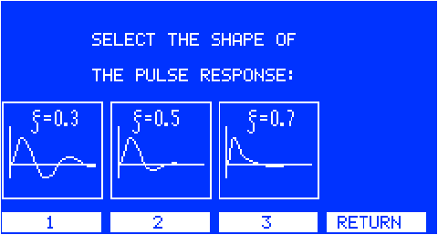 |
The Pulse Response of the Operated Channels can be Adjusted Automatically within 10 Seconds per Channel. |
ON-LINE HELP |
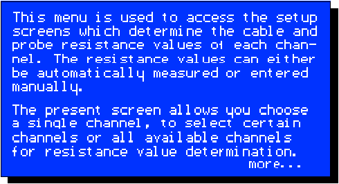 |
Immediate Visual Context-sensitive Help is available at the Touch of a Button at any Time from Any Menu Screen. |
- System Configuration:
The AN - 2000 can be used with Any Type of Film / Wire Probe, with upto Eight Channels in the Mainframe and Eight Additional Channels in an Expansion Chassis. Channel Types may be CCA/CTA or Analog Input Channels. The DMA / RS-232 Card Interfaces between the AN - 2000 and any of the 486 / PENTIUM Family of Computers. A High Current Power Supply Unit may be added to Boost Probe Current (recommended for Measurement in Water). All Hot-wire Sensors may be Calibrated Automatically using the CAL - 2000 Digital Air Speed Calibrator.
The AN - 2000 Supports a Wide Variety of External Transducers. In Addition, its PC Software is able to Control Traverse Systems of 6 Axes and Sample Data to the Hard Disk while moving the Traverse Unit.
- CAL - 2000 Digital Air-Speed Calibrator:
The CAL - 2000 is a High-precision Digital Air Speed Calibration System designed especially for the Calibration of Hot-wire and Hot-film Sensors. It’s Powerful Motor Generates Air Velocities of 1 to 70m per second over Varying Temperature, Humidity and Barometric Conditions. For further details kindly visit: CAL - 2000
- Software (AN - Flow):
- Introduction:
The AN-FLOW Software Program provides a Multi-function PC Based Interface to the AN-2000. In Addition to Remote Access and Operation of the Anemometer, the AN-FLOW Enables Real Time Display of Data Sampled by the Channels being Operated, Application of the built-in Functions on that Data (such as Fourier Decomposition), Data Smoothing and Statistical Functions. It also enables Direct Storage of Sampled Data to Disk in a Number of File Formats. The Graphical User Interface Provides Intuitive Access and User Friendly Operation of All Functions, using either Keyboard or Mouse.
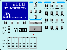 |
REMOTE CONTROL |
 Remote Control Operation Software provides Full Control Over the Instrument, including Setup Functions, Bridge Balancing, Signal Conditioning, etc.
|
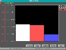 |
BAR DISPLAY |
Dynamic Velocity / Voltage Distribution Bar-Graph. |
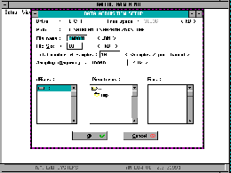 |
DATA ACQUISITION |
High Speed Data Acquisition System Saves the Sampled Data into Binary or ASCII Files on your Hard-disk. Upto 1000 Files, upto 1000KB/File can be Saved. |
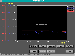 |
SCOPE DISPLAY |
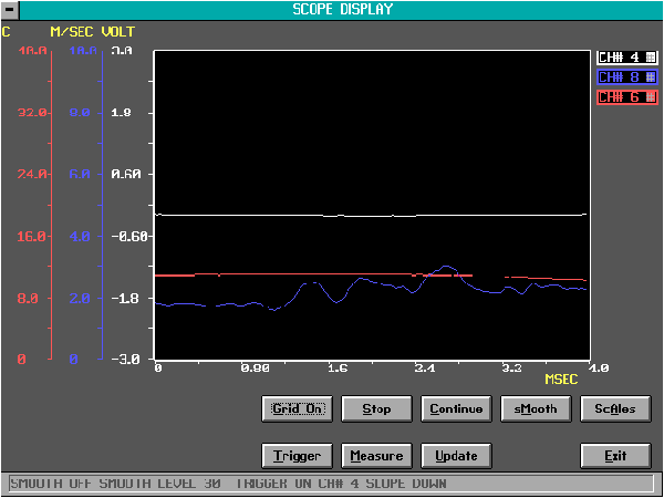
Simultaneous, Real-time, Scope-like Display of upto 16 Signals, with 3 Scales. |
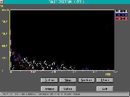 |
F.F.T. |
Fast Fourier Transform allows Frequency Analysis of upto 16 Channels in Real-time. FFT
Data may be Saved to File. |
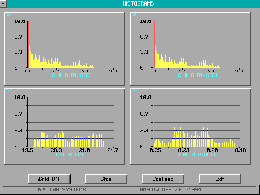 |
HISTOGRAM |
Real-time Histogram Display of upto 4 Channels Simultaneously with Over-range Display. High Resolution Display with 100 Bars, 3000 Samples/Channel. |
 |
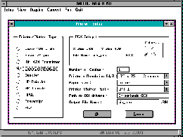
PRINTING |
Printing and Exporting of Files to Various Printers and Graphic Formats. |
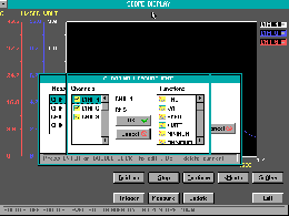 |
MEASUREMENT |
Upto Four Different Real-time Measurements can be Attached to any of the Operated Channels and displayed in Scope Window. |
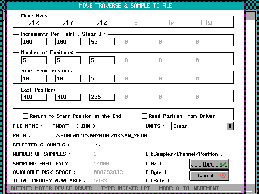 |
TRAVERSE CONTROL |
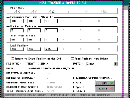
ANFLOW Software Enables you to Control upto Six Stepping Motors Simultaneously, move them from One Position to Another (upto 1000 Positions) and Sample a Data File in Each Physical Point (Position). The Measurement Points (Positions) may be Defined as a Six-dimensional Grid or along a Six-dimensional Path that you will Define. |
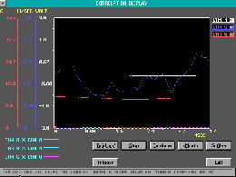 |
CORRELATION |
On-line Cross-correlation Display of Any Two Channels, upto 4 Channel Pairs. Correlation Function is Displayed in Bold line. The Software supports Three Linear Axes (X, Y, Z) and Three Angular Axes (Theta, Phi and Omega). The Position of the Sampling Point is Recorded into the Data Acquisition File for the User’s Reference and Exporting to PROFLOW Profile Generator. ANFLOW can interface with any External Stepping Motor Controller that Supports RS-232 Interface or use Pulse and Direction Signals for Control (Optional Driver). |
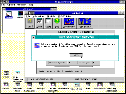 |
LINFLOW: PROBE CALIBRATION |
Calibration of a variety of Sensors is made easy using LINFLOW Software. Calibrate almost any type of Probe: 1, 2 or 3 Wires, with any angle between Sensors. Calibration can be Manual using your Flow, or automatic using the CAL-2000 Digital Air Speed Calibrator.
Our Smart Calibration Algorithm enables Single Sensor Calibration within 20 seconds. The Calibration Model is based on Jorgensen's Equation which by taking into account Flow Condition, Noise and Other Parameters, Increases the accuracy of the Calibration. |
 |
PROFLOW: PROFILE GENERATOR |
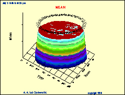
The PROFLOW Software Generates 2-D and 3-D Velocity Profiles within Few Minutes, from your ASCII Data Files, Sampled in Different Physical Locations. Graph Types includes: Mean, RMS, FFT, Turbulence Intensity, Temperature, Humidity, etc. |
 |
LABVIEW SOFTWARE INTERFACE |
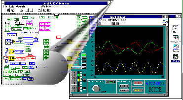
The AN-2000 also supports Remote Access Control and Operation by LABVIEW Software. Three different VI’s are supplied with the AN-2000 Software Package. They Enable the User to make on-line Measurements, Acquire Data to Disk and Control the Instrumentation.
This Modular Software Allows Editing, Adjustment and Customization according to requirements. Fully Documented Source-code is provided with all Modules. |
 |
WINDOWS VERSION |
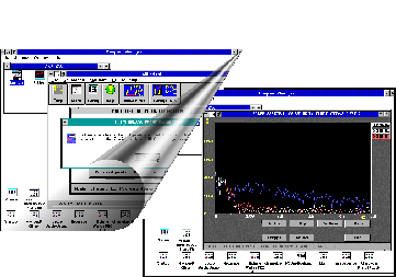
WINDOWS 3.1 & WINDOWS 95 Versions of ANFLOW and LINFLOW provide a User Friendly Interface for Operation and Calibration of the Sensors and Acquiring Data to Disk. All Software Versions are fully featured and are supplied on a CD-ROM. Free Upgrades for 3 Years are available at No Charge. |
 |
ONLINE HELP |
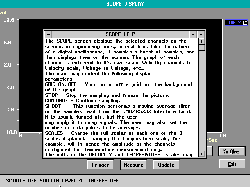
On-line HELP is available with all AN-FLOW and LINFLOW Screens. Text-Sensitive, Immediate Assistance and Support at your Fingertips. |
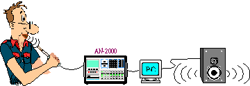 |
RECORD AND PLAY |
PLAY utility enables you to "Record" sounds using your Hot-Wire Probe, Store them into a File and Play them back using a Standard "Sound Blaster" Compatible Card. |
- High Standards High Speed Friendly
State-of-the-art microprocessor architecture, based on the industry standard microprocessor gives the AN-2000 the ability to perform high speed display and control operations as well as complicated floating-point arithmetic calculations. Data acquisition is performed by proprietary hardware designed for high reliability Direct-Memory-Access (DMA) transfers at high rates.
The USB2 interface is an ultra high speed interface running at up to 480 Mb/Sec. The USB2 interface is capable of controlling the AN-2000 from any PC compatible computer running Windows XP. The user may operate the AN-2000 remotely (up to a distance of 200m from the host PC), send commands, set the gain, offset, filtering and bridges of all channels and acquire data from the AN-2000 in all modes (Acquisition mode, pulse response etc.).
- Analog Signals and Anemometers: What YOU Should KNOW

STANDARD ANEMOMETRY System
The most common configuration today (see Figure 1) is an analog instrument (usually controlled via RS-232), that produces voltage proportional to the flow. This instrument is generally connected via a signal conditioner module to the data acquisitions card via long cables. The data acquisition system is a PC (or MAC) interface card, and shares the same ground as the host computer. These typical analog instruments and PC configurations connected to the same ground result in random appearances of strange noises and spikes on low level signals, even 50Hz or 60Hz spikes on some signals. Each spike input to the system via the same ground as the sensor results in an “overshoot”.
The experienced user recognizes these “Pulse” or “Square Wave” response curves. In the event that there is a “train” of such impulses from multiple sources and the PC ground is shared by the sensor (via the data acquisition system), all of the current spikes generated by the PC will appear in the signal.
Hardware interruptions caused by DMA refresh of the memory, writing to the disk, mouse & keyboard use; switching power supply spikes (50 - 80 kHz), and VGA refresh. These contribute to a noisy environment not conjunctive to accurate data acquisition.
Despite the fact that an analog anemometer has been specified to work upto 50 kHz, the user finds that it has a -3dB response of 20kHz only. These systems do not process data channels simultaneously and most of the important phase information is lost. When requesting support from the supplier one is ultimately told that the problems encountered result from “other system components”. The same response is generally given by the supplier of the other system components. Unfortunately it is more often than not, a familiar scenario with no simple solution. These systems work appropriately when separate, on data acquisition, the DC levels of the analog system tend to fluctuate, and even movement of the mouse during sampling causes strange random spikes to appear on the data. These expensive 16/12 bit data acquisition PC cards sample data at 10 bit readable resolution only... however, when integrated they can become unstable, inaccurate and unreliable.

Solution: USE OUR AN-2000 COMPUTERIZED ANEMOMETER TO AVOID THESE PROBLEMS
- SMARTWARE - the Breakthrough:
As a result of years of rigorous field experience in measurement and data acquisition in research institutions and industry worldwide, the engineers of A.A Lab Systems offer multi-platform compatible, user friendly, high tech solutions:
- Years of research brought about the evolution of a new approach by A.A Lab Systems, to the data acquisition of anemometry signals, i.e. placing the entire data acquisition system on different electrical grounds. The key word is Optical Isolation. There is no connection at all between the analog ground and the digital ground of the AN-2000 (isolation of more than 2 Mega Ohm resistance!).
- All of the signal conditioning and data acquisition are done inside the channel module, where the signal path is only 3cm (compared with 2-5m of cable in other systems).
- Sampling is true simultaneous at rates of 93 kHz, 160 kHz and higher (per channel).
- The frequency response is automatic, Bode plot display is real-time and dynamic according to user adjustments.
- The data measured with the built-in data acquisition system is linearized and correct up to the last bit.
When measuring only mean values of your flow, a Hot-Wire/Film anemometer may not be required. However, when you want to measure the velocity fluctuations of your flow and require more detailed data, such an instrument is essential. Most users need to measure dynamic signals. The frequency range might be from few hundreds of Hz up to 500 kHz. When you measure those high speed velocity fluctuations you need to know two things:
- That your measurement system is capable of measuring those fluctuations accurately and correctly.
- That all signals measured are on the same time base. You must ensure that both occur in order to know that your measurements are precise and reliable.
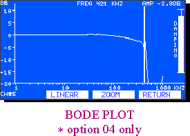
Our High Frequency compensation option (04) scans all frequencies in the range of 1kHz to 1MHz. exhibiting the correct response graph in the Frequency domain. This plot gives you detailed information about the total frequency characteristics of your system: Is it flat in all of the frequency range? Are there any oscillations (or a response which might lead to oscillations in a higher velocity?). What is the actual frequency range you might measure with your current sensor? All of those parameters may be adjusted on-line by the user.
- Simultaneous Sampling:
Simultaneous sampling is another important feature for dynamic signal processing. A non-simultaneous data acquisition system will lead to phase errors between the signals, after they are reconstructed. Those errors might be from few degrees in very low frequencies to 180 degrees if a high sampling rate is used in conjunction with a large number of channels. The simultaneous sampling feature of the AN-2000 allows you to sample at the highest sampling rates, with NO phase errors. You can correlate between the Temperature, Velocity and external signals WITHOUT worrying about the accuracy of your results.
The built-in low-pass filters are self-calibrated to have the same cut-off frequency on all channels. This means that all channels will have the same delay, no matter how old is the electronics or what is the Temperature today... You may repeat this calibration at any time.
- Soft Start Circuit:
How many times did you try to connect a 1.2 micron wire to your anemometer only to find that it was burned before you could measure with it? The AN-2000 is one of the few instruments in the world capable of protecting the probe due to its unique Soft Start circuit. In regular anemometers, each channel is operated by a switch or relay for closing the control loop. This operation creates “ringing” and oscillations which burn out delicate wires. The AN-2000 eliminates this problem with a unique proprietary bridge start circuit, which protects your very delicate sensors from being burned. It also incorporates additional circuits for the protection of sensors in case of power failure, manual power discontinuation or user malfunction.
- Technical Specifications:
C.T.A Bridge |
C.C.A Bridge (Option 05). Constant Current Type (in addition to CTA mode) |
Non-Linear Constant Temperature Type |
Bridge Current (in 256 equal steps) |
0.5 - 50mA |
Bridge Ratio: |
1:10 and 1:1 |
Setup Accuracy |
±0.5% |
Sensor Resistance Range |
Temperature Drift |
100ppm/°C |
1:1 Bridge: |
0.3 - 200Ω (Ohm) |
Channel A/D Converter (Option 08) |
1:10 Bridge: |
0.3 - 20Ω (Ohm) |
Sampling Method: |
Simultaneous S&H |
Probe Lead Resistance Compensation: |
0 - 4.0Ω (Ohm) |
Sampling Rate: |
0 - 93kHz, 0 - 160kHz or 0 - 500kHz (optional) |
Resistance Measurement Accuracy: |
±0.01Ω (Ohm)
±0.05% |
Clock Source: |
Internal or External |
Maximum Closed Loop Bandwidth |
External Trigger: |
Edge or Level Trigger |
1:1 Bridge: |
DC - 120kHz (upto 500kHz with option 04) |
Resolution: |
14 bit |
1:10 Bridge: |
DC - 120kHz (upto 550kHz with option 04) |
Digital Linearizer (OPTION 09)
This option is available only if Option 08 is installed |
Probe Current |
Output Resolution: |
16 bit |
x1 Drive |
300mA Max. |
Input-Output Delay: |
100nSec |
x2 Drive |
*600mA Max. (*Option 02 is required for more than 6 channels simultaneously, up to 1.8A per sensor is available on request) |
Output Resolution is Higher than Input Resolution, in order to prevent errors caused by Polynomial Calculations |
Equivalent Input Noise |
All polynomial graphs and coefficients are calculated using floating point arithmetic's |
1:1 Bridge |
1.6nV/√Hz |
All channels have analog "Top Of Bridge" and "Signal conditioner" outputs on BNC connectors |
1:10 Bridge |
2.2nV/√Hz |
Control Unit |
With option 01 |
400pV/√Hz |
All analog parts are optically isolated from the digital parts and use separate power supplies |
Typical Hum induced in input |
0.03µVrms |
Dot Matrix Display |
Typical Output Noise |
Resolution |
256(W) x 128(H) Pixels |
5µm Tungsten Probe, R=3Ω (Ohm), OHR=1.5, U=0
B.W = 10kHz |
135µVrms |
Viewing Area |
108(W) x 58(H) mm |
The same, with option 01 |
60µVrms |
Dot Size |
0.4 x 0.4 mm |
Stability - Typical Input Drift |
Backlight Color |
Gray-Blue |
1:1 Bridge |
0.4µV/°C |
A/D Converter
(For Frequency response and scope only!) |
1:10 Bridge |
0.3µV/°C |
Sampling Rate |
15MHz |
With option 01 (all bridge ratios) |
0.1µV/°C |
Resolution |
8 bit |
Probe Cable |
5m of RG174 or RG58A upto 8m of cable with option 04, 20m optional |
All signals displayed are sampled by the control Unit A/D converter |
Output |
Top of bridge buffered |
Acquired data which is sent to the parallel DMA port is sampled by the channel's A/D converter (14 bits) |
Signal Conditioner |
Interfaces |
Output Voltage Range: |
±12V |
RS - 232 Serial Interface: |
Standard |
Amplifier Gain (256 discrete settings): |
1 - 99.9 (Other gain values may be ordered) |
Baud Rates: |
1200, 2400, 4800, 9600 and 19200 |
Gain Accuracy: |
±0.2% |
DMA parallel interface compatible with:
DRV-11 Connector:
Display Bus: |
Standard
Standard |
DC Offset: |
±10V (in 5mV steps) |
Analog outputs |
Top of bridge, buffered, amplified & filtered output |
Output Impendence: |
100Ω (Ohm) |
Throughput Rate: |
Up to 1.6 MegaWord/Sec(10MW optional) |
Input Impendence: |
10KΩ (kOhm) |
External Clock Input: |
DC - 90kHz, TTL Level (DC - 160kHz or DC - 500kHz Optional) |
Typical Input White Noise: |
30nV/√Hz |
External Trigger Input: |
TTL Level |
Frequency Range: |
DC - 200kHz |
External Sync Input (for Ensemble averaging): |
TTL Level |
Typical Equivalent Input Drift (Gain 1): |
160µV/°C |
Operation Voltage: |
230V/115V
50/60Hz switchable |
Low Pass Filter |
High Pass Filter |
4'th order Butterworth Filter with 512 Cut-off frequencies: |
100Hz - 120kHz (Other frequency bands can be ordered) |
2 Second Order High-Pass filters, switchable on back panel |
All filters have linear phase and are self-calibrated to have the same delay on all channels |
Cut-off frequencies |
1Hz, 10Hz |
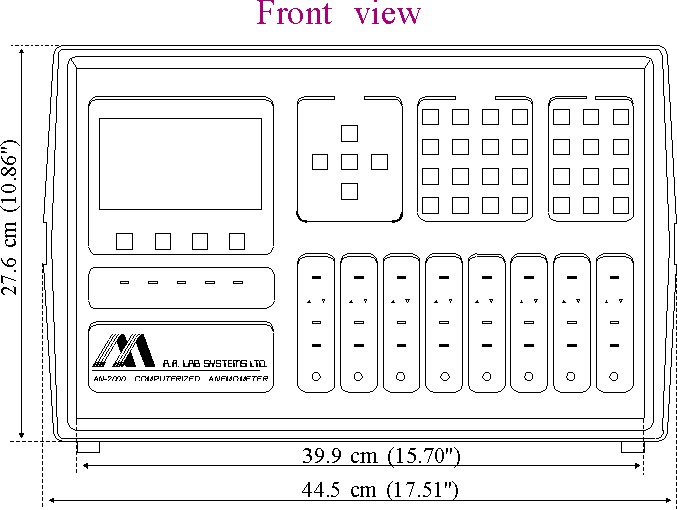
- Mainframe Dimensions:
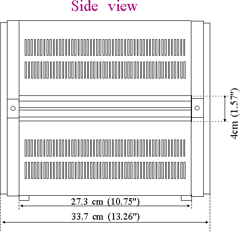
- Different Options Available for AN - 2000 Hot Wire Anemometer System:
Upto 20 different options may be added to the basic instrument configuration. Designed for specific research requirements, these options dramatically enhance the standard instrument configuration. These Options allow you to hand-pick the system you really need on a channel-by-channel basis, without having to choose between "all-or-nothing". We recommend that you consult the factory or us about your application and the options required for that.
- Ultra-Low Noise Amplifier (Option 01):
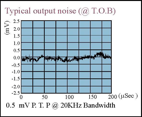 Adapted from the bridge circuitry of the highly successful AN - 1003 Anemometer, this high performance, low noise, bridge amplifier has two substantial features not found in any “off the shelf” amplifiers: Adapted from the bridge circuitry of the highly successful AN - 1003 Anemometer, this high performance, low noise, bridge amplifier has two substantial features not found in any “off the shelf” amplifiers:
- A very low noise voltage with a spectral density of 400 pico Volts per root of Hertz (pV/√Hz) compared to the 1500 to 2000 pV/√Hz found in "Low Noise" commercial amplifiers (1.2 nV/√Hz).
- A very stable input with a very low offset voltage drift, as low as 0.1µV/°C (micro Volt per degree Centigrade) resulting in an ultra low noise CTA anemometer, with almost zero drift. This option provides a precise and accurate Top of Bridge voltage and an excellent Signal-to-Noise ratio.
 High Current Power Supply (Option 02): High Current Power Supply (Option 02):
A Mainframe Option: For operation of upto 8 probes in the high current mode (maximum of 600mA per probe)
- Expansion Unit (Option 03):
 A slave unit which increases the AN-2000 capacity by 8 channels. Includes power supply and all necessary cables for connection to a master mainframe. A slave unit which increases the AN-2000 capacity by 8 channels. Includes power supply and all necessary cables for connection to a master mainframe.
- High Frequency Compensation (Option 04):
Extends the frequency response of each channel to 500kHz. The frequency compensation option consists of both hardware and software that enable the user to adjust the sensor, to get the widest, flattest frequency response possible. This exhibits the response of the CTA bridge to a Sine Wave input into the bridge itself (after attenuation).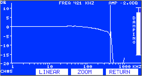 This Sine Wave input simulates a change in the heating/ cooling of the sensor and its response will be relative to the low frequency response (1kHz in our case). The response test can be repeated as often as required while the user adjusts the cable compensation circuit and the damping control simultaneously. Also available for cable length upto 15m. This Sine Wave input simulates a change in the heating/ cooling of the sensor and its response will be relative to the low frequency response (1kHz in our case). The response test can be repeated as often as required while the user adjusts the cable compensation circuit and the damping control simultaneously. Also available for cable length upto 15m.
- Constant Current Mode (Option 05):
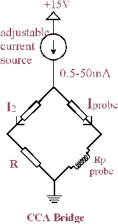
Provides CCA mode probe operation in addition to the standard CTA mode. Bridge current is 0.5 - 50mA. The CCA Bridge is usually used for rapidly varying temperature measurements. Unlike Thermistors or Thermocouples, which have a high heat capacity, large volume and slow response, the CCA circuit measures temperature fluctuations at frequencies of 2kHz and higher, with accuracy better than 0.1°C. The sensor wire's diameter may be 2 microns or even less. The Temperature to Voltage ratio of the CCA circuit is linear and temperatures of upto 800°C can be measured. The temperature of a CCA channel can be displayed or saved to a file in addition to the velocity information, allowing the user to make temperature compensation to the velocity measurements.
- A/D Converter (Option 08):
A 14-bit resolution A/D converter for each channel with maximum sampling rate of 93 kHz per channel (sampling rate can be changed by software). Data output: 15 bits, DMA interface (similar to DRV-11). New high speed A2D's available: 160 KHz. per channel, 500 KHz. per channel.
- Digital Linearization (Option 09):
Provides data linearizer (output linear to velocity), installed in each channel, 16 bit resolution. Linearization is digital, with no added noise/offset/drift etc. Option 08 must be selected with this option.

Specialized firmware, custom designed, is incorporated into the AN-2000. It supports the hardware in each channel as well as software for calibration and measurement in the PC, enabling sampled signals to be converted into digital linearized data and subsequently transferred, in real-time to the PC. This feature allows the user to “see” the velocity and temperature fluctuations on the PC's screen. Comprise correlations and spectrums, and store them on the hard disk in engineering units. This form of digital linearization, which is carried out at 70nSec, uses a high resolution lookup table which is formed digitally. The noise, drift and time consumption characteristic of analog linearizers and standard A/D cards is eradicated. These unique properties endow the AN-2000 linearizer with a level of accuracy and reliability not attained by any other method of calibration.
- High Speed USB2 Interface (Option 10):
This option is a powerful, high speed USB2 interface working at 480 Mb per second. The USB2 interface is capable of interfacing between the AN-2000 and any PC compatible computer running Windows XP. The interface provides control of all AN-2000 functions including high speed data acquisition. The interface can extend the distance between the AN-2000 and the host PC to a distance of up to 200m.
- Battery Operation (Option 12):
For uninterrupted operation. Includes rechargeable battery with built-in charger. Can support system operation for more than two hours without mains current.
- AN-FLOW Software (Option 13):
A 14-bit resolution A/D converter for each channel with maximum sampling rate of 93 kHz per channel (sampling rate can be changed by software). Data output: 15 bits, DMA interface (similar to DRV-11). New high speed A2D's available: 160 KHz. per channel, 500 KHz. per channel.
- SPD-500 Data Transceiver Unit (Option 14):
For transferring the DMA and display data to distances of 5 - 200m from the host computer. The SPD-500 Data Transceiver consists of two separate units which can transmit and receive digital data at high speeds over a distance of 600 feet (200 m), using standard twisted-pair ribbon cable. These transceivers relay the data, and the graphic display generated by the AN-2000 to the remote PC.

- Additional 1MB RAM (Option 15):
This option is obsolete and not needed with the USB2 interface.
- CAL - 2000 Digital Air Speed Calibrator (Option 16):
For calibrating sensors in Air, at 1-70m/Sec. Standalone instrument with operation software. Click CAL - 2000 for more information.
- Analog Input Channel (Option 17):
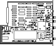
For Acquiring external analog signals together with the velocity and temperature provided by other channels.
- High Speed A/D Converter (Option 18A or B):
For sampling rate of 160kHz per channel (A) or 500kHz per channel (B) (simultaneous sampling).
- Ultra-High Current Power Supply (Option 19):
For driving eight sensors at up to 0.7 Amp each. Including modification of bridge ratio to support high current.
- Traverse:
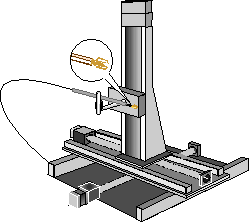
The PC software of the AN-2000 is able to control Traverse systems of 6 axes and sample data to the hard disk, while moving the Traverse unit. Traverse Control: ANFLOW software enables you to control up to six stepping motors simultaneously, move them from one position to another (up to 1000 positions) and sample a data file in each physical point (position). The measurement points (positions) may be defined as a six-dimensional grid or along a six-dimensional path that you define.
All Specifications are subject to change without a Prior Notice
For any sort of clarifications kindly contact:
info@globesolutionz.com
|