High Voltage / Piezo Amplifiers & Signal Conditioners
Fiber Optic Links / Data Acquisition Systems
RF Power Amplifiers / Dual Directional Couplers
Instruments for Biological Science
Under Water Metal Detectors, Camera’s & Sonar Systems
|
Fiber Optic Links
AFL - 4800 High Speed Analog / Digital Fiber Optic Link
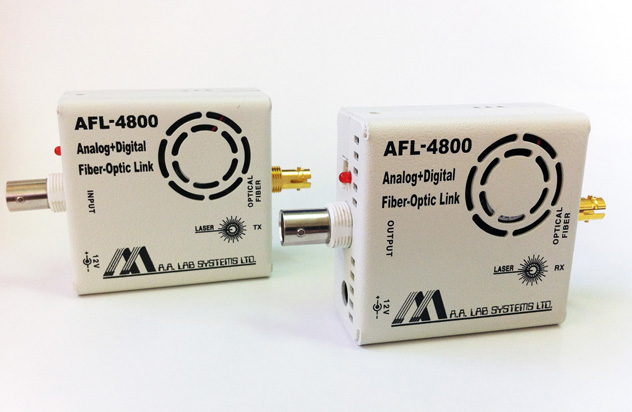
The Product is Very Small in Size (Box Size): 61 * 61 * 29mm. Weight: 120 grams
The AFL - 4800 is an Enhanced Fiber Optic Transmission Product Family, used for Transmission of 1 Analog Channel + 2 Digital Channels to One Direction. The Product is based on A/D and D/A Technique, combined with a Powerful Transceiver, for ranges of upto 50km, at Analog Bandwidth of upto 25MHz, at 14-bit Resolution (84dB digital S/N Ratio). The Product Exist in 3 Grades: Frequency Bandwidth of DC - 8MHz, BW of DC - 15MHz and BW of DC - 25MHz
Both Digital and Analog Channels are Sampled Simultaneously to provide Correct Phase Signal for Analysis, Control and Data Acquisition Purpose, especially when High Data Rates are Transmitted (Encoder A and B Signals, Serial Data + Clock, etc.).
By combining Fiber Optic Technology with Advanced Proprietary Hardware, we provide Researchers and Industry with the means to isolate 1 Analog + 2 Digital Signals from Electrically Hostile Environment, Transmit it over upto 50km (using SM Fiber, 5km with MM Fiber) to the Data Acquisition System, while Conditioning the Signal. This method eliminates the Addition of EMI / RFI Noises generated by Electrical Machinery, Line Noises, Ground Loops and Digital Noise to your Analog Signals.
- Applications:
- Transfer of Analog Signals from a Noisy Environment
- Isolation of the Signal from High Voltage Sources
- Eliminating Ground Loops
- Accuracy and High Signal / Noise Ratio
- Remote Data Acquisition and Control
- Excellent System Reliability
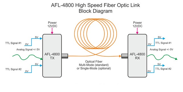
The Following Drawing describes the Signal Inputs and Outputs to the AFL - 4800 Link
- Features:
- Excellent Signal Isolation.
- Prevents Ground Loops and Computer Noise Effects on your Analog Signals.
- Transfers Analog Signals to distances of upto 100km.
- Linearity: Better than 0.01%.
- Low Noise S/N Ratio (DC - 1MHz): 82dB
- Input Signal: Upto ±5V @ upto DC - 25MHz
(Maximum Signal Level with No Damage: ±7V)
|

|
- Advantages:
- Low Noise Transfer of Analog or Digital Data (such as DCLS GPS Signals or Ultra-fast Trigger) particularly beneficial in Electrically Noisy Environments and for Transmission over Long Distance.
- Very Low Delay: 350nS + 5µSec per km for Analog Signals.
- Transmit Signals from High Speed Sensors such as: ECG, Temperature, Humidity, Pressure, etc.
- Isolates Delicate Test Equipment from Computer generated Noise and Spikes: Noises from Computer do not return into your System.
- Eliminates the formation of “Ground Loops” (when Two Instruments are connected to Separate Power Lines or have a difference between their Ground Voltage Potentials).
- Total Protection of Signal Processor’s Input Stage from Accidental Sensor Malfunction (e.g. Short to Mains Voltage or a Lightning Shock).
- Replaces bulky coaxial cables with compact Fiber Optic Cables - Especially Important when rewiring existing ducts.
- Cheaper Wiring (for Long Distances) than Standard Copper Cable. 1 Analog Channel + 2 Digital Channels on a Single Fiber!
- Transfers Analog and Digital Signals to distances of upto 50km - with Very High Accuracy
Analog Inputs |
Input Voltage Range: |
−5V to +5V
(−1V to +1V available per request) |
Sampling Resolution: |
14 Bit |
Sampling Frequency: |
125MHz |
Link Speed (Optical): |
2.5GHz |
Noise and Hum induced in Input: |
Less than 2 Millivolts RMS
(DC - 15MHz) |
Sampling Method: |
True Simultaneous Sampling |
Input Impedance: |
1KΩ Standard, 50Ω Optional |
Analog Bandwidth: |
Is set per Customer’s Request |
Please Note that Analog Bandwidth in NOT Half of the Sampling Rate!
Internal Low-Pass Filters are not Ideal! |
Analog Outputs |
Output Voltage Range: |
−5V to +5V
(−1V to +1V available per request) |
Resolution: |
14 Bit |
Noise and Hum Induced in Output: |
<1 Millivolt RMS
(DC - 15 MHz) |
Delay from Input to Output: |
350 nano Seconds for Analog Signal
(DC - 15 MHz) |
Output Impedance: |
100Ω Standard, 50Ω Optional
(Amplitude Limit: ±4V)
|
Digital Inputs and Outputs |
Number of I/O Signals: |
2 Inputs / 2 Outputs |
Sampling Rate: |
125MHz |
Sampling Method: |
True Simultaneous Sampling |
Delay from Input to Output: |
250nSec Constant Delay |
- Options:
- Option 01 (Single Mode Optics): This Option is for using Single-mode Fibers. The Option offers an Optical Budget of 16dB’s which is good for about 20km of Single-mode Fiber (9/125 Microns Fiber).
- Option 02 (50 Ohms Input Termination): This Option is a High Precision 50 Ohms Resistor installed directly on the Input BNC Contact for proper termination for RF Signals. A Termination of 75 Ohms (for Video Signals) can be installed instead of 50 Ohms. Please Notice that if you are using a Standard Function Generator with this option (which also has a 50 Ohms Output Impedance), It would Load the Generator and cut the Amplitude of Each Signal to Half (compared to the Amplitude Viewed on a High Impedance Oscilloscope with No 50 Ohms Termination).
- Option 03 (50 Ohms Output Driver): This Option offers a High Current Driver for driving 50 Ohms Cables Terminated by a 50 Ohms Resistance. Because of the Driver Limitations, the output would be Limited to ±4V only.
- Option 04 (High Frequency Bandwidth − DC − 15MHz): This Option is an Input ⁄ Output Bandwidth of DC − 15Mhz.
- Option 05 (High Frequency Bandwidth − DC − 25MHz): This Option is an Input ⁄ Output Bandwidth of DC − 25Mhz. This Option can be installed only if Option 03 is selected.
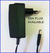
AFL - 4800 - PS1:12V, 1.5A, Regulated Power Supply
(For 1 AFL - 4800 Unit)
|
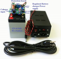
AFL - 4800 - BAT:
Battery Operated Power Supply
Can Run 1 Unit for upto 5 Hours
(Available in OEM version)
|
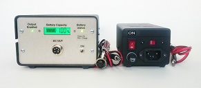
Battery Operated Power Supply
Housed in a Metal Case
|
- Rack Mounting (AFL - 4800 Rack):

19″ Rack Front

19″ Rack Back
Upto 5 AFL - 4800 Units may be Installed into a 19″ Compatible Aluminum Rack Enclosure.
The 19″ Enclosure Height is 3U, it is Self-Ventilated and Low Weight
All Specifications are subject to change without a Prior Notice
For any sort of clarifications kindly contact:
info@globesolutionz.com
|