High Voltage / Piezo Amplifiers & Signal Conditioners
Fiber Optic Links / Data Acquisition Systems
RF Power Amplifiers / Dual Directional Couplers
Instruments for Biological Science
Under Water Metal Detectors, Camera’s & Sonar Systems
|
Fiber Optic Links
AFL - 300 Digital Fiber Optic Link
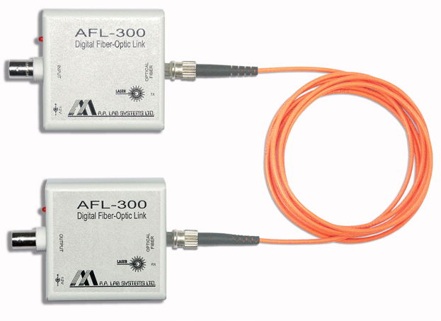
Actual Size: 61 * 61 * 28mm (Box Only)
- AFL - 300 Digital Fiber Optic Link is the right choice when you need to:
- Transfer a Trigger Signal from a Noisy Environment.
- Isolate the Signal from High Voltage Sources.
- Eliminate Ground Loops.
- Transfer Precise Timing over a Long Distance.
- Have Excellent System Reliability.
The AFL - 300 Digital is an Excellent Solution for Transmission of Precise Timing Signal over Optical Fibers. Those Signals can be Triggering Signals, Synchronization Signals, GPS Timing Signals and any other TTL Compatible Signals (0 to 5V or 0 to 12V).
The input to the AFL-300 is a logic input, 0 to 5V or 0 to 3.3V (0 to 12V per request).
The signal is transferred over the optical fiber with minimum latency and almost zero jitter. The signal is reconstructed on the receiver and can be output as a TTL signal (0 to 5V), 0 - 12V signal or open collector (up to 30V external voltage).
- The AFL - 300 Consists of the Following Components:
- A Digital Fiber Optic Transmitter: AFL - 300 DIG / TX
- A Digital Fiber Optic Receiver: AFL - 300 DIG / RX
- Upto 3km of of Multi-mode Glass Fiber or 50Km of Single-mode Fiber (Optional)
- Optical Budget with Single-mode Transceivers: 28dB
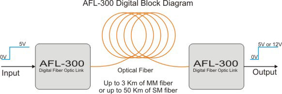
The Link is Connected between the Signal Source at the Transmitter and the Signal Output at the Receiver
- Features:
- Transmit Precise Timing Signals over Optical Fiber.
- Prevents Ground Loops and Computer Noise Effects.
- Transfers Analog Signals to distances of upto 3km (50km with Single-mode Transceivers).
- Excellent Signal Isolation.
- Short Propagation Delay: 200nSec + 5µSec/km.
- High Frequency Bandwidth: DC to 10MHz.
- Very Small Size: Only 61 * 61 * 28mm
- Low Cost
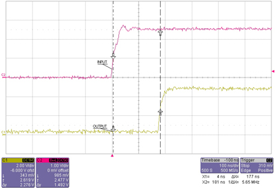
Rising Edge (100nSec/Div.)
|

|
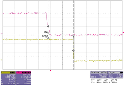
Falling Edge (100nSec/Div.)
|
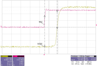
12V Output (200nSec/Div.)
|
- Technical Specifications:
Input / Output Range: |
±5V Standard;
Input is compatible with 0 to 3V Logic as well;
Output can be switched by user between 0-5V to 0-12V to Open Collector. |
Jitter: |
Low Jitter: Upto 300pSec, using MM Fiber |
BETTER JITTER SPECS ON REV.#D UNITS |
Using SM Fiber the Jitter is less than 100pSec on the Rising Edge and in Most Frequencies or Pulse Width it is the same on the Falling Edge. On Few Particular Frequencies the Jitter on the Rise Time only might be upto 45nSec. This can be adjusted by the factory so it would not interfere with your signals. It may be reversed by the factory to have Low Jitter on Fall Time and Higher Jitter on Rise Time |
Frequency Response: |
DC to 15MHz |
Noise: |
Low Output Noise |
Supply Voltage: |
12V Regulated, Floating Power Supply; 24V Optional |
Optical Fiber: |
Glass, 62.5/125 Micron Dia. Standard (upto 3km)
ST Connector Standard
Single Mode Fiber (Optional): 9/125 Micron, ST Connector |
Transmission Range: |
Upto 3km Standard (MM Fiber)
50Km Optional with Single-mode Fiber |
Optical Budget with Single-mode Transceivers: |
28dB |
Voltage Isolation |
Input to Output: |
Infinite Voltage Isolation |
Input / Output to Mains: |
Standard 800V, Optional upto 2500V |
Battery Operated: |
Infinite Voltage Isolation |
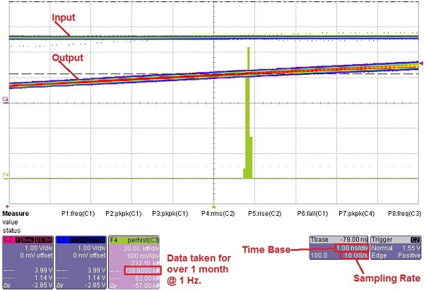
Oscilloscope Error is 1 / Sampling Rate = 100pSec.
Jitter is lower than 100pSec.
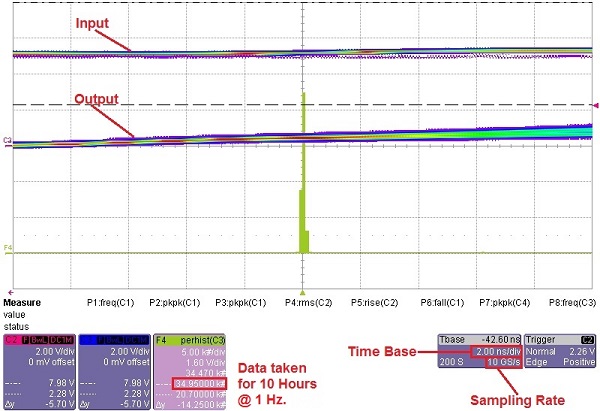
Oscilloscope Error is 1/Sampling Rate = 100pSec.
Jitter is lower than 300pSec.
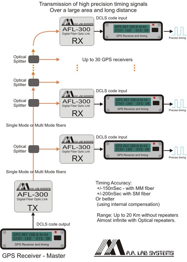
Synchronization of GPS Receivers to produce Precise Timing Signals:
Master GPS receiver is transmitting precise timing signals in IRIG-B002 DC Level Shift format (DCLS) to other receivers. Receivers are compensated for transmission delays and create precise, synchronised timing signals and timing code.
- Ordering Information:
- The AFL - 300 Digital is Available with Single-mode Optics or Multi-mode Optics.
- Input Range is TTL (0 - 3V or 0 - 5V). Output Range can be adjusted by User (0 to 5V, 12V or Open Collector). Other Input and Output Ranges available per request (0 - 12V, 0 - 24V, etc.)
- A Stabilized Power Supply is also required for Each Side. It can supply Power for upto 5 (Optionally 10) Receivers or Transmitters.

AFL - 300 - 05: 5 Channel Power Supply
(For one side)
|
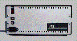
AFL - 300 - 10: 10 Channel Power Supply
(For One Side)
|
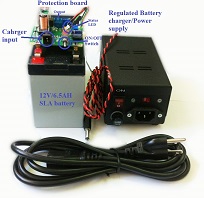
AFL - 300 - BAT:
(Battery Operated Power Supply)
Can run upto 5 Channels for upto 10 Hours. Includes a 12V / 6.5AH Battery, Charger + Cables. Larger Batteries with Higher Capacity are available.
(Available in OEM version)
|
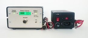
Battery Operated Power Supply
Housed in a Metal Case
|
- Rack Mounting (AFL - 300 Rack):

19″ Rack Front

19″ Rack Back
A Standard 19″ Rack Mounting Case for upto 10 AFL - 300 Units (Receivers or Transmitters)
With ON/OFF Switch and Power Supply / Charger Input
All Specifications are subject to change without a Prior Notice
For any sort of clarifications kindly contact:
info@globesolutionz.com
|