High Voltage / Piezo Amplifiers & Signal Conditioners
Fiber Optic Links / Data Acquisition Systems
RF Power Amplifiers / Dual Directional Couplers
Instruments for Biological Science
Under Water Metal Detectors, Camera’s & Sonar Systems
|
Fiber Optic Links
AFL - 284 DIN Rail Fiber Optic Link
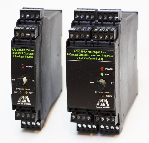
AFL - 284 DIN Rail Analog / Contact Closure Fiber Optic Link is an OEM product designed especially for Industrial Applications.
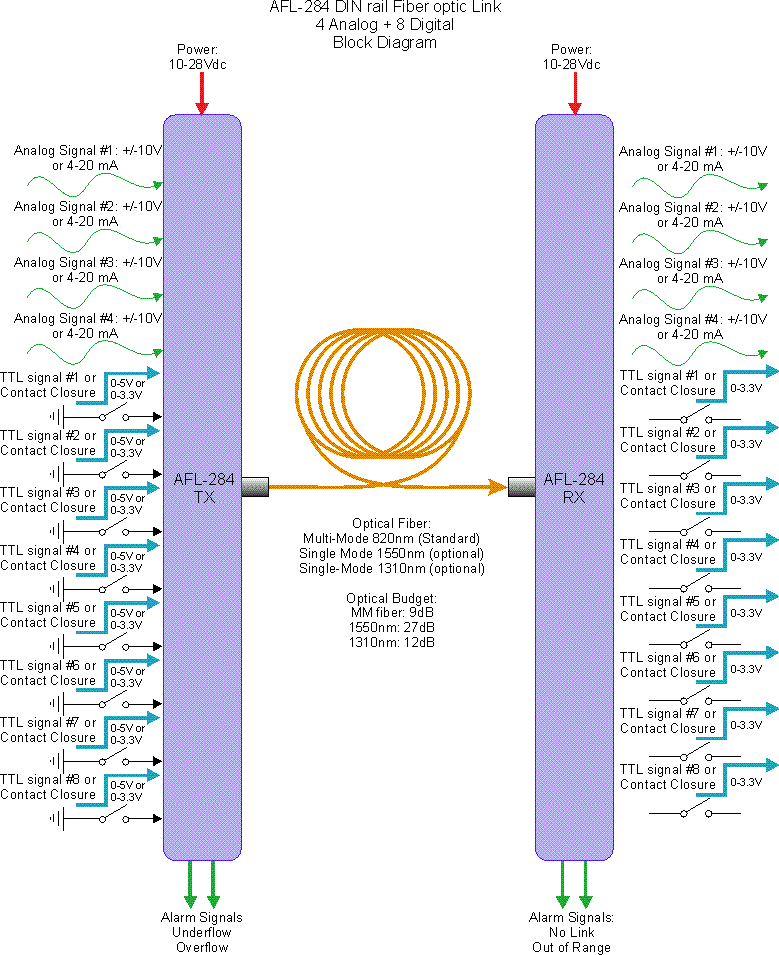
The Fiber Optic Link units may be used for transferring 4 (Four) Analog Signals of ±10V or 4 - 20mA current loop signals, together with 8 (Eight) Contact Closures (or Digital / TTL Signals). Each one of the Analog Signals can be configured separately to be ±10V or 4 - 20mA. Digital Inputs can be optionally adjusted to 0 - 12V or 0 - 24V Logic Levels. Each one of the Digital Outputs can be adjusted to Logic Input or to Contact Closures.
The user may configure the Analog Input to be -10V to +10V or 4 - 20mA by using jumpers (Per Channel). The Receiver Units will Output both − Voltage or 4 - 20mA signals (for input range of 0 to +10V or 4 - 20mA, as selected) alongwith 4 - 20mA current loop signal.
The 8 Digital I/O lines may be also configured by the user to 0 to +5V (or +3.3V) Standard TTL Signal or to Contact Closure (i.e. a contact closure at the transmitter would cause a contact closure at the receiver).
It is possible to invert all of the contact closures using a single jumper (i.e. an open contact would yield a closed contact at the receiver end and vice versa). Same option is available for TTL signal: 1-> 0 and 0->1.
The AFL - 284 Analog / Contact Closure Fiber Optic Link was designed for system integrators and builders, where low size, low power consumption and low cost are important. You won't have to keep 3 - 4 different fiber optic links in your toolbox. One link does it all with few simple jumper configurations.
No need to lay few fibers - One fiber would transfer all signals.
The bandwidth of the analog inputs is DC - 7kHz. The contacts can be switched up to 50 times per second and the TTL lines can be toggled up to 20,000 times per second. The distance between the Tx and Rx modules may be between 0 to 2 miles with the standard Multi-Mode interface (30 miles optional with 1550nm Single Mode optical interface and SM fiber).
- AFL - 284 Block Diagram:
- Features:
- Excellent Signal Isolation.
- Prevents Ground Loops and Computer Noise Effects on your Analog Signals.
- Transfers Analog Signals to a Distances of upto 3km (50km Optional).
- Linearity: Better than ±0.05%.
- Low Noise S/N Ratio: 84dB @ DC - 10kHz.
- Input Signal: Upto ±10 Volt @ DC - 7kHz or 4-20mA @ DC - 7kHz.
- 8 Contact Closure Signals with 125VAC @ 0.5A or 24VDC @ 1A Rating.
- Wide Input Power Range: 10 - 28VDC.
- Low Offset Temperature Drift: Better than 15ppm/°C
- Very Small Size: Tx: 22.5 mm width Rx: 45 mm width
- Low Cost
- Flexible Analog and Digital I/O Configuration (±10V and 4 - 20mA mixed, TTL/Contact closures Mixed)
- Overflow and Underflow Alarm LEDs + Open Collector Signals at the Transmitter.
- Out of Range and No Link Alarm LEDs + Open Collector Signals at the Receiver.
|

|
- Advantages:
- Low Noise transfer of Analog or Digital Data, particularly beneficial in Electrically Noisy Environments and for Transmission over Long Distance.
- For Industrial Applications: DIN Rail Interface, 24V Single Supply.
- Analog Inputs can be Mixed: 0,4 or 1,3 or 2,2 or 3,1 or 4,0 Inputs of ±10V, 4 - 20mA.
- Digital inputs can also be mixed between 0 - 3.3V, 0 - 5V, 0 - 12V, 0 - 24V or Contact Closures at any combination.
- Isolates Delicate Test Equipment's from computer-generated Noise and Spikes: Noises from Computer do not return into your System.
- Eliminates the Formation of "Ground Loops" (when two instruments are connected to separate power lines or have a difference between their ground voltage potentials).
- Total Protection of Signal Processor's Input Stage from accidental sensor malfunction (e.g. short to mains voltage or a lightning shock).
- Replaces bulky coaxial cables with compact fiber optic cables - especially important when rewiring existing ducts.
- Interface to existing fibers - Multi-Mode Standard, Single Mode Optional.
- Transfers Analog Signals to a Distances of upto 50km - with 15.5 bits Accuracy. (14 bit + 1.5 bits more due to oversampling and resolution enhancement technique).
- Technical Specifications:
Analog Input Range: |
±10V or 4 - 20mA |
Analog Bandwidth: |
DC - 7kHz |
Analog Output Range: |
±10V or 4 - 20mA |
Digital Bandwidth: |
DC - 20kbps |
Non-Linearity Error: |
0.05% @ ±10V Range |
S/N Ratio
DC - 10kHz: |
84dB |
Noise: |
Better than 2.5mV RMS |
Supply Voltage: |
10V - 28V |
Input Impedance: |
1 Giga Ohms (FET Amp) (Analog) CMOS Inputs for Digital I/O |
Supply Current: |
RX: 300 - 410mA, TX: 300mA @ 12V.
Lower Current at Higher Supply Voltage |
Optical budget with Single Mode Transceivers: |
27dB |
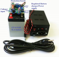
AFL - 284 - BAT:
(Battery Operated Power Supply)
Can run upto 2 Rx or 1 Tx units for upto 24 Hours. Includes a 12V / 9AH Battery, Charger + Cables. Larger Batteries with Higher Capacity are available.
(Available in OEM version)
|
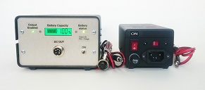
Battery Operated Power Supply
Housed in a Metal Case
|
- Rack Mounting (AFL - 284 Rack):
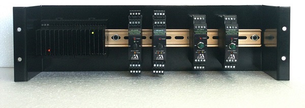
19″ Rack Enclosure: 19″ Rack Enclosure is Available for Housing upto 12 Tx Modules or 6 Rx Modules and a Power Supply or more modules with external Power Supply.
All Specifications are subject to change without a Prior Notice
For any sort of clarifications kindly contact:
info@globesolutionz.com
|