High Voltage / Piezo Amplifiers & Signal Conditioners
Fiber Optic Links / Data Acquisition Systems
RF Power Amplifiers / Dual Directional Couplers
Instruments for Biological Science
Under Water Metal Detectors, Camera’s & Sonar Systems
|
Thermal Anemometry
AN - 1003 Hot-Wire Anemometry System

A Hot-Wire Anemometer is an Instrument for Measuring Fluid Velocity, Whether it be of Gases or Fluids, Hot-Wire or Hot-Film, Hot-Wire Anemometers measure Fluid Speed using a Delicate Probe made of Thin Tungsten / Platinum Wire, or a Thin Metallic Film. This Probe is Heated to a Temperature Higher than Average Temperature of the Fluid. Using Sophisticated Circuitry, the Anemometer Stabilizes and Maintains the Probe Temperature at a Constant Level throughout the Measurement. Since the Fluid Flowing past the probe has a Lower Temperature than the Probe, the Film / Wire is Constantly being Cooled by the Fluid Flow. The Higher the Velocity, the Faster the Rate of Cooling.
Since the Anemometer must Maintain the Probe Temperature at a Constant Level, it is therefore Sensitive to the Rate at which it is being Cooled, i.e. the Fluid Velocity. This Velocity is Translated to a Continuously Changing Voltage which has a Nonlinear Relationship with the Flowing Fluid. This Voltage then undergoes Signal Conditioning, to Filter Out Noise and Improve the Signal / Noise Ratio.
After Proper Calibration of the Probe Channels, it is Possible to Measure Fluid Velocities with an Accuracy of 0.05% or Greater, depending upon the Measurement Range and the Quality of the Calibration. The Response Time between Measurement and Instrument Output is Very Short in Comparison with Other Methods of Fluid Flow Measurement and can reach a Minimum of 1/2µSec. The AN - 1003 Anemometry System measures at that Speed upto 10 Channels Simultaneously!
- Features:
- Easy Operation
- Low Noise: Less than 2.2 nV/√Hz
- Ultra Low Noise Option: Less than 400pV/√Hz
- Intelligent Modular Design
- CTA and CCA in a Single Channel (Optional)
- Probe Protection Circuit
- Soft-start Circuit for Delicate Probes
- High Frequency Response: DC - 100kHz Standard, DC - 500kHz Optional
- Flexible: May be used with Hot-Film and Hot-Wire
- Built-in Signal Conditioner:
- Controllable Gain
- DC Offset, Adjustable to Any Value
- Noise Filter: Low Pass Filter With 12 Cut-off Frequencies
- Built-in Indicators Aid User in Balancing the Bridge
- Built-in Square Wave / Pulse Generator
- Fail-Safe Switches
- Self-maintained, No Expensive Servicing required
- 12-months Parts & Labor Warranty
|

|
- Advantages of AN - 1003 Hot-Wire Anemometer System:
The AN - 1003 Hot-Wire Anemometer can Measure Fluid Velocities from 0 and upto Supersonic Speeds. In Addition to these Inherent Qualities of the basic AN-1003 System, there are 14 Extra Options which can be Added to Any Number of Channels. These Expand the Capabilities of the System, Allowing it to make Professional-Standard Measurements in Different kinds of Fluids.
Another Advantage of the AN - 1003 is it’s Modularity: Channels can be Removed or Interchanged without Disturbing Other Channels already Calibrated for Different Experiments.
The AN - 1003 is being used today at a Large Number of Leading Research Institutes and Universities throughout the World, where, for a Number of Years, it has Proved it’s value as a Reliable and Accurate Instrument, and has become a Valuable Research Tool for Scientist’s and Engineer’s. Part of the AN - 1003’s success is due to its User Oriented Design, making the System Easy and Straightforward to Use by inexperienced Students and Professional Researchers alike. We hope that you become part of this expanding group of Satisfied AN - 1003 Users.
Refer to the Technical Specification to find out about the outstanding capabilities and characteristics of the AN - 1003. As a result of Technological Advances in Design and Production, we can Now Offer you a Complete AN - 1003 Anemometry System at a Substantially Lower Price than in the Past, making this Highly Reliable and Accurate System Highly Affordable as well.
- Technical Specifications:
CTA BRIDGE
Non Linear, Constant Temperature Type |
Bridge Ratios: |
1:10 and 1:1 |
High Power Mode: |
1:20 and 1:2 |
Sensor Resistance Range |
1:1 Bridge: |
0.5 - 99.9Ω (Ohm) |
1:10 Bridge: |
0.5 - 9.99Ω (Ohm) |
Probe Lead Resistance Compensation: |
0.2 - 1.2Ω (Ohm) |
Maximum Closed Loop Bandwidth |
1:1 Bridge: |
DC - 120kHz |
1:10 Bridge: |
DC - 100kHz |
With Option 04: |
DC - 500kHz |
Probe Current |
x1 Drive: |
300mA Max. |
x2 Drive: |
600mA Max. |
Equivalent Input Noise |
1:1 Bridge: |
1.6nV/√Hz |
1:10 Bridge: |
2.2nV/√Hz |
With Option 01: |
400 pV/√Hz |
Typical Hum Induced in Input: |
0.03µVrms |
|
All Noise Parameters are Correct for One or All Channels Working Simultaneously |
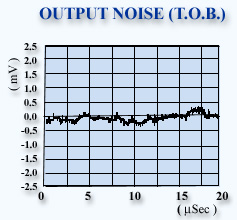
Typical Output Noise |
5µm Tungsten Probe, OHR=1.5, U=0, B.W.=10kHz: |
135µVrms |
The same, with option 01: |
60µVrms |
Stability - Typical Input Drift |
1:1 Bridge: |
0.5µV/°C |
1:10 Bridge: |
0.3µV/°C |
With Option 01 (All Bridge Ratios): |
Less than 0.1µV/°C |
Probe Cable: |
5m of RG174 or RG58A |
Output: |
Top of Bridge or Amplifier Output |
CCA BRIDGE
Constant Current Anemometer, OPTION 11 |
Fixed Currents: |
1, 2, 5, 10, 20mA |
Variable Current Source: |
0.3 - 30mA |
|
Selected Current is Displayed on Test-Module |
SIGNAL CONDITIONER |
Output Voltages Range: |
±12V |
Amplifier Gain (Pre-settable to Any Gain in Range): |
1 - 20
(Can be Ordered with 1 - 50 or 1 - 1,000 Ranges) |
Gain Accuracy: |
±0.5% |
DC Offset: |
0 - 10V |
Output Impedance: |
100Ω (Ohm) |
Input Impedance: |
10kΩ (kOhm) |
Typical Input White Noise: |
30nV |
Frequency Range: |
DC - 100kHz |
Typical Equivalent Input Drift (Gain 1): |
160µV/°C |
LOW-PASS FILTER
Triple-Pole Butterworth Filter, with 12 Cut-off Frequencies in 2 bands |
Lower Band: |
300Hz - 5kHz (6 Frequencies) |
Upper Band: |
7Hz - 16kHz (6 Frequencies) |
|
Other Frequency Bands can be Ordered |
Mainframe Specifications |
POWER SUPPLY |
Output Voltages: |
±15V, ±5V |
Maximum Current (@ ±15V): |
4A (7A with Option 10) |
Hum and Noise: |
100µVrms |
|
Can Drive 10 Channels @ 1:10 Bridge Ratio or 5 Channels @ 1:1 Bridge Ratio.
Option 10 Can Drive All Ten Channels in 1:1 or 1:10 Modes, Simultaneously. |
TEST MODULE |
Pulse Generator |
Frequency Voltage: |
2kHz |
Duty Cycle: |
50% or 0.2% |
Rise Time: |
50nSec |
Output Voltages: |
0.1V |
Accuracy: |
100ppm/°C, 0.1% |
Function Selects: |
Automatic Input / Output Connection According to Selected Function |
Channel Selector: |
Digitally Controlled, Gold Plated Contacts |
|
In Normal Operation, All Channels except One are Disconnected from the Test Module, to Prevent Additional Noise Inputs from External Devices or Cross-talking
All Noise Parameters are Correct for One or All Channels Working Simultaneously |
The Hot-Wire Anemometer Works with Almost any Hot-Wire Sensor and Hot-Film Sensor made by Any Manufacturer |
|
|
The Typical Frequency Response Sine Wave Test Graph was Plotted According to Data taken from AN - 1003 Hot-Wire Anemometer with Options 01 & 04. The Amplitude is Normalized and relate to the 1kHz Amplitude. |
1mV P.T.P. @ 200kHz Bandwidth |
- Options:
Option 01: |
ULTRA LOW NOISE INPUT AMPLIFIER |
400PicoVolts/√Hz
Less than 0.1mVrms Output Noise on 0 - 20kHz Bandwidth |
Option 03: |
TEMP. COMPENSATION - Discontinued |
Use Option 11 Instead |
Option 04: |
FREQUENCY COMPENSATION |
A Tunable Circuit for Improving the Frequency Response upto 500kHz |
Option 05: |
BACKUP BATTERIES |
Provides Operation Without Mains Current for More than 2 Hours. Built-in Charger Included. |
Option 06: |
FILTER BANDS |
Other than Specified. Please Specify Upper and Lower Cut-off Frequencies in Each Band |
Option 07: |
GAIN OPTION |
Other than 1 - 20. Please Specify Maximal Gain required |
Option 09: |
DC OFFSET MEASUREMENT |
On the Test Module with External BNC Output |
Option 10: |
HIGH CURRENT POWER SUPPLY |
Capable of Driving upto 10 Probes in 1:1 Bridge Ratio as well as in x2 Mode (upto 600mA per Channel) |
Option 11: |
CCA (Constant Current Anemometer) in Addition to CTA Mode |
With 31 Fixed Current Levels and a Variable Current of 0.3 - 30mA |
Option 12: |
HIGH PERFORMANCE SIGNAL CONDITIONER |
Gain of 1 - 100 (1 - 200 Optional) With 1 - 10 Variable Control and a Gain Multiplier of x1, x2, x5, x10. High Accuracy DC Offset (2ppm/°C Stability) with a Variable Control of 0 - 2V + Fixed Steps of 0, 2, 4, 6, 8 Volts. DC-off Function. Use for Low Velocities and Low Turbulence Levels |
Option 13: |
EXTERNAL POWER SUPPLY REMOVAL KIT |
For Removing the Power Supply to an External Rack for Ultra High Noise Immunity |
Option 14: |
AUTO-ZERO DC OFFSET |
For Automatic Reduction of DC Offset (Use for Velocity Profiles or Near Wall). Control Signals are TTL Compatible (Zero + Read DC Offset) |
Option 15: |
PROBE CABLE |
5m RG-58 COAXIAL PROBE CABLE |
Notes: |
1. Probe protection and soft start circuits are standard on all channels.
2. All mainframes are built for 115/220Vac 50/60 Hz operation.
|
All Specifications are subject to change without a Prior Notice
For any sort of clarifications kindly contact:
info@globesolutionz.com
|